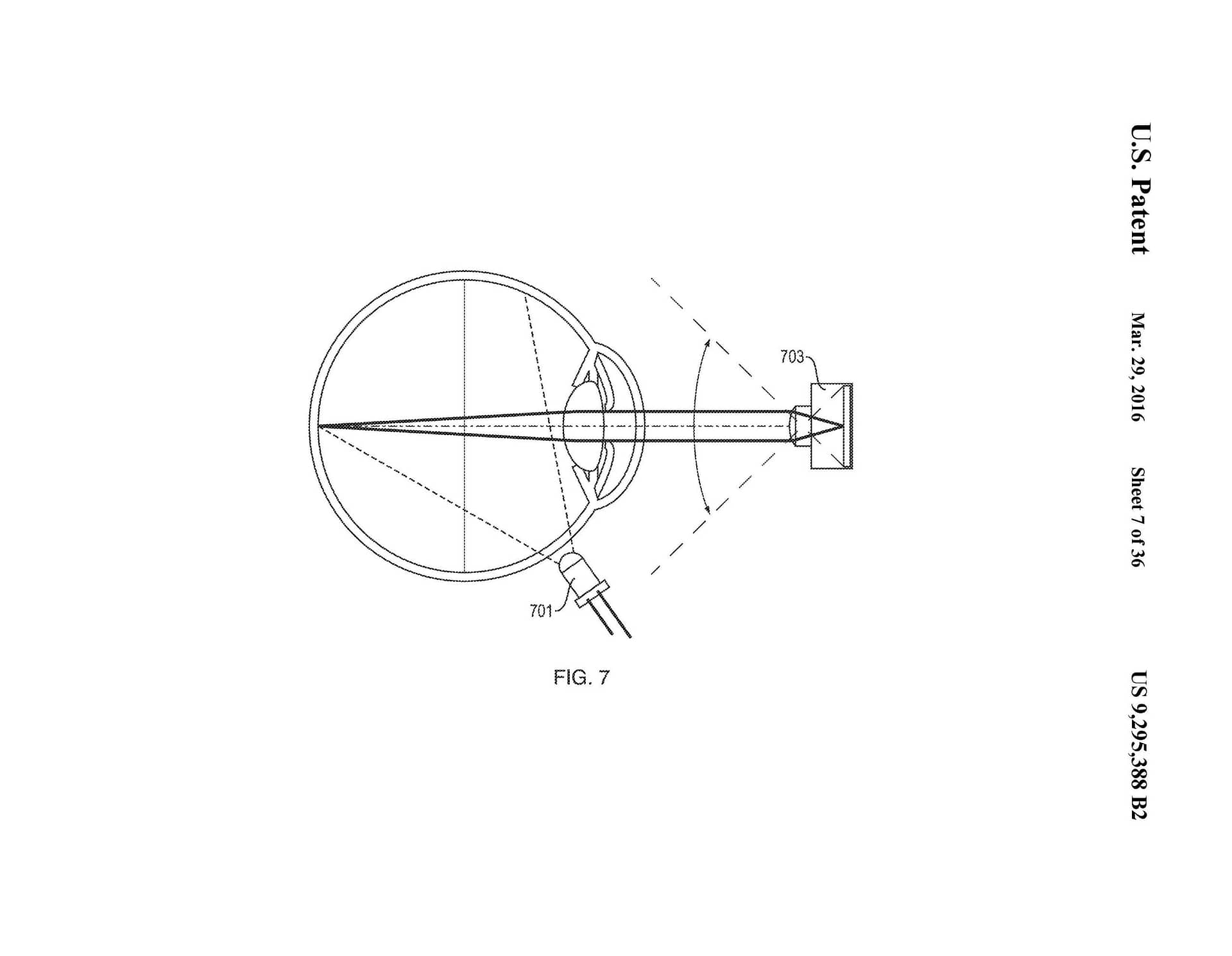
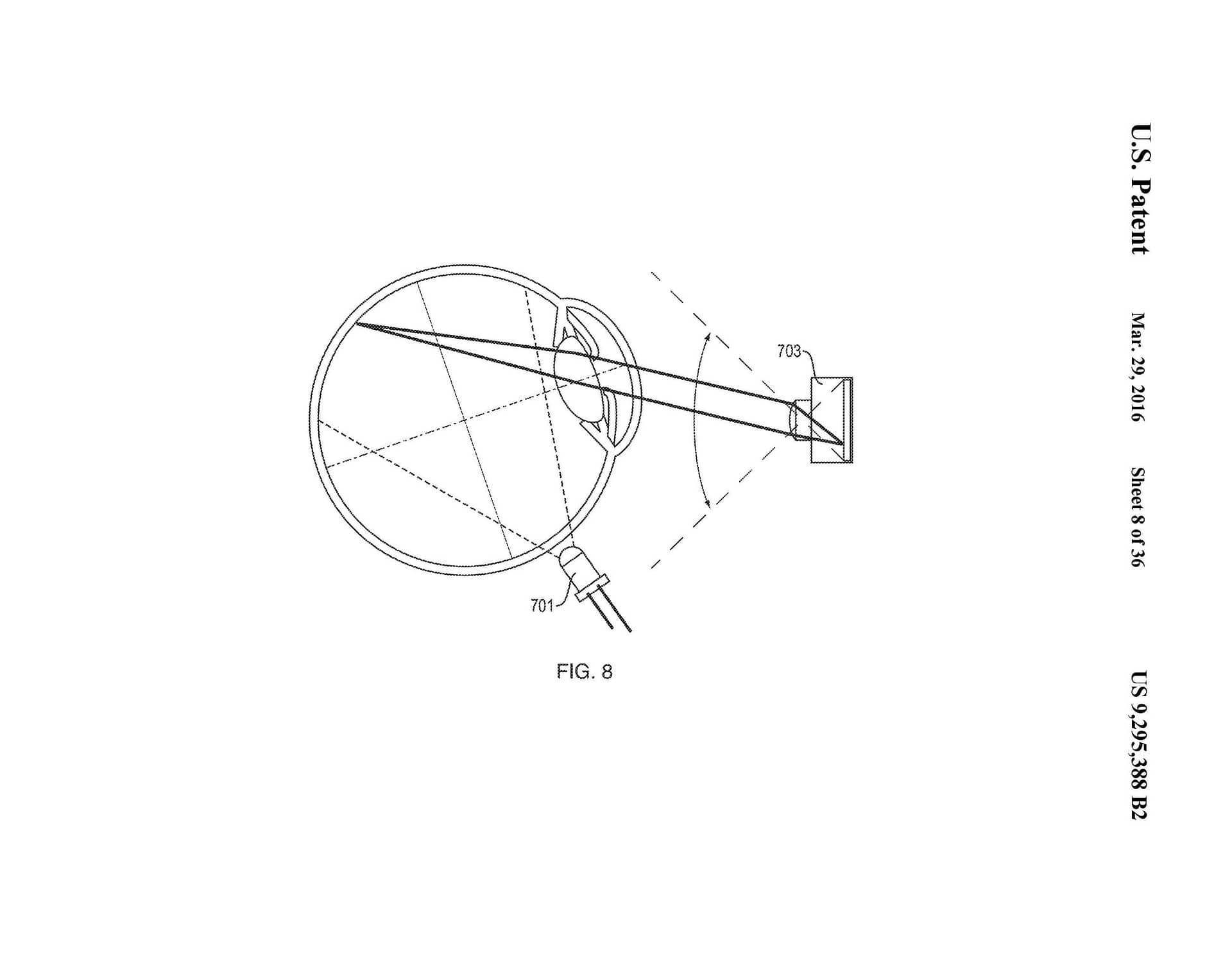
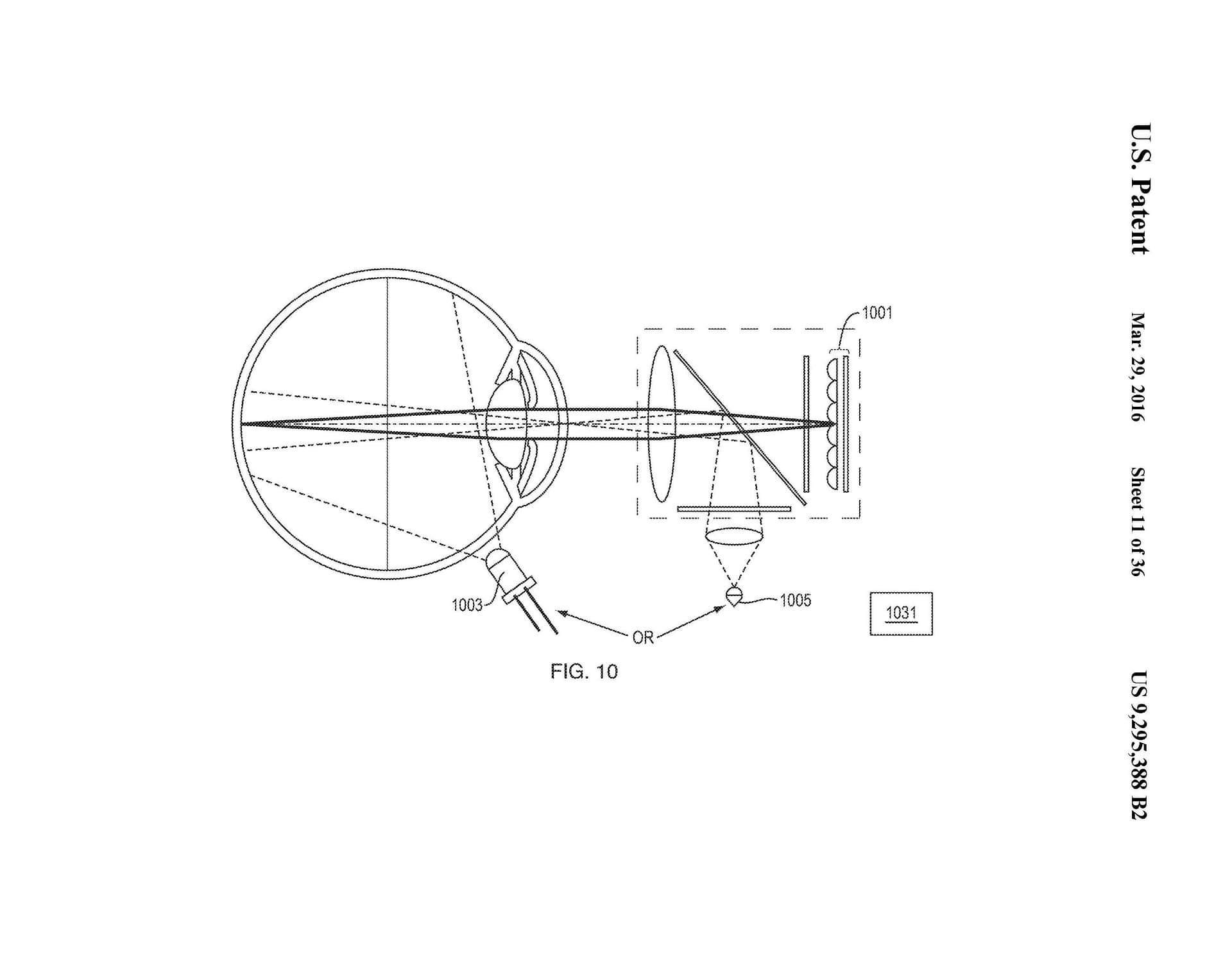
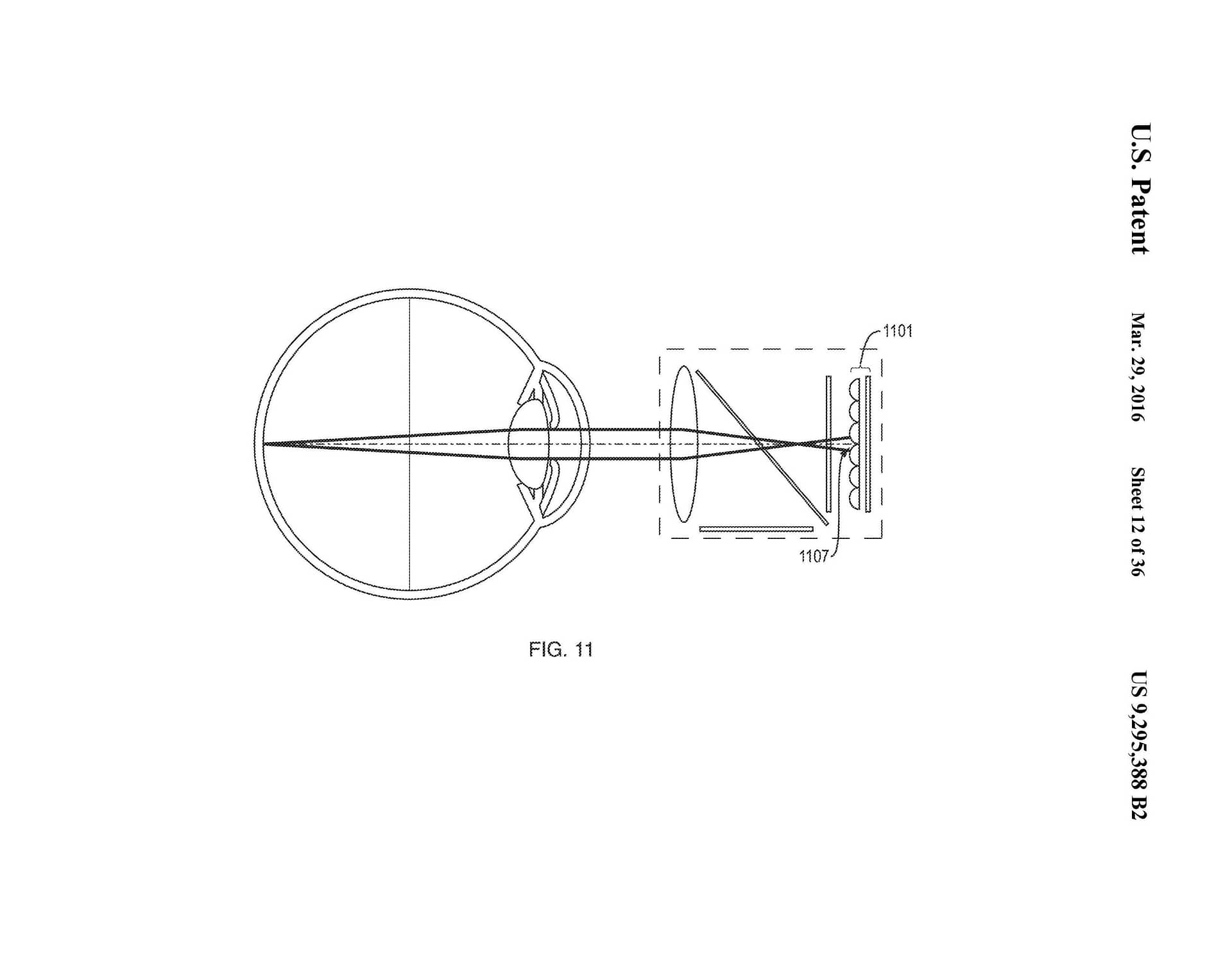
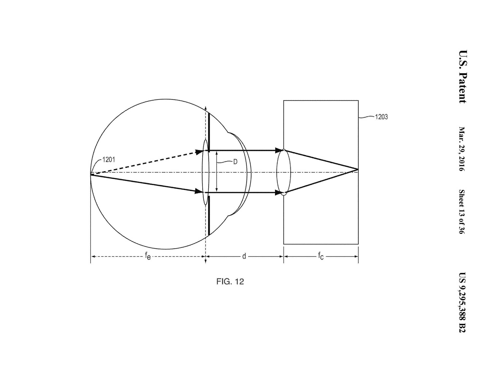
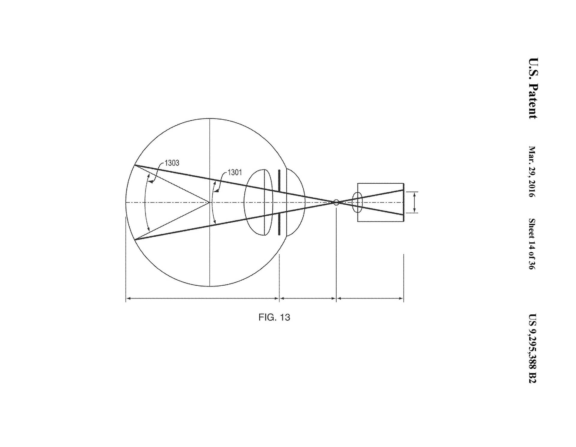

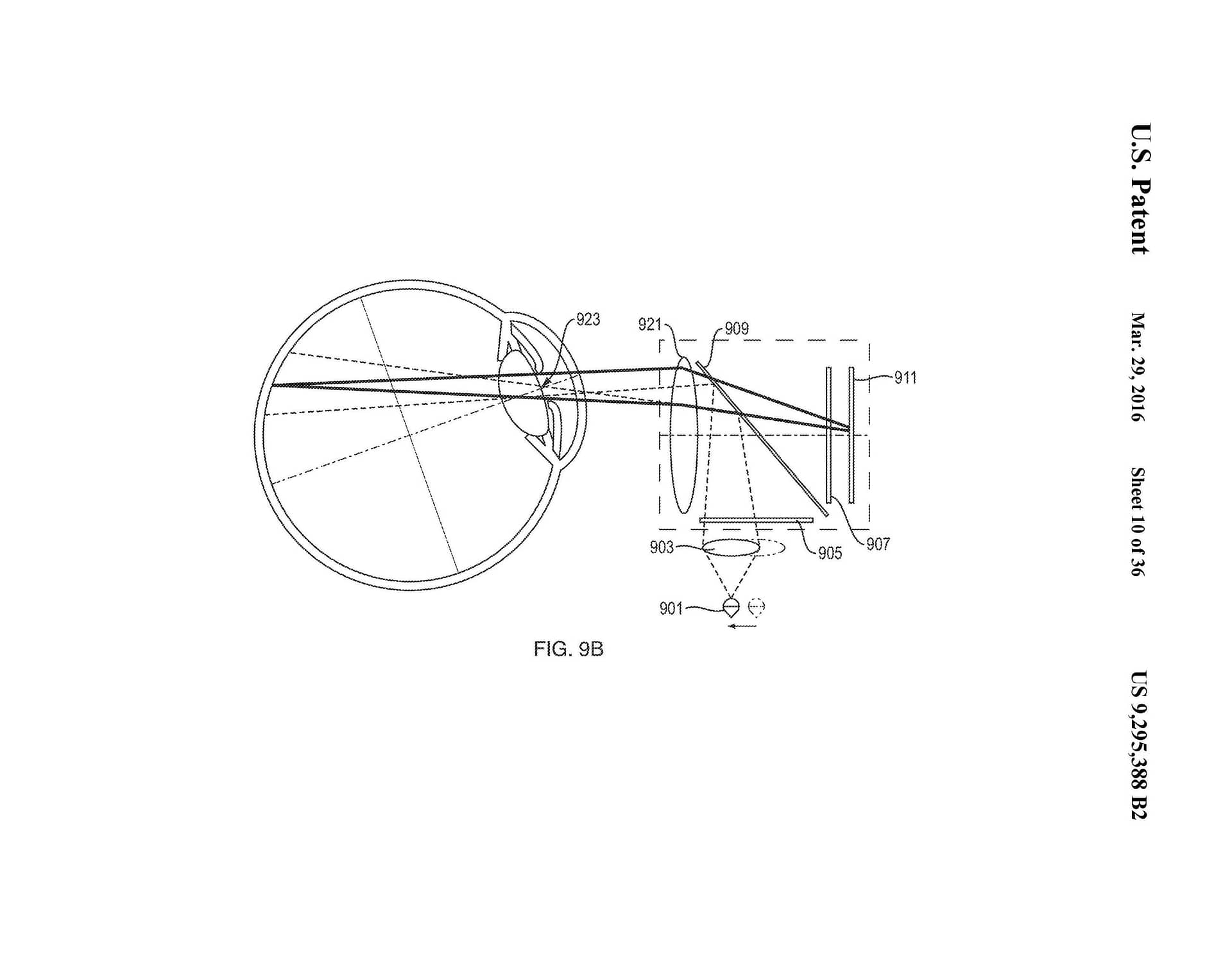
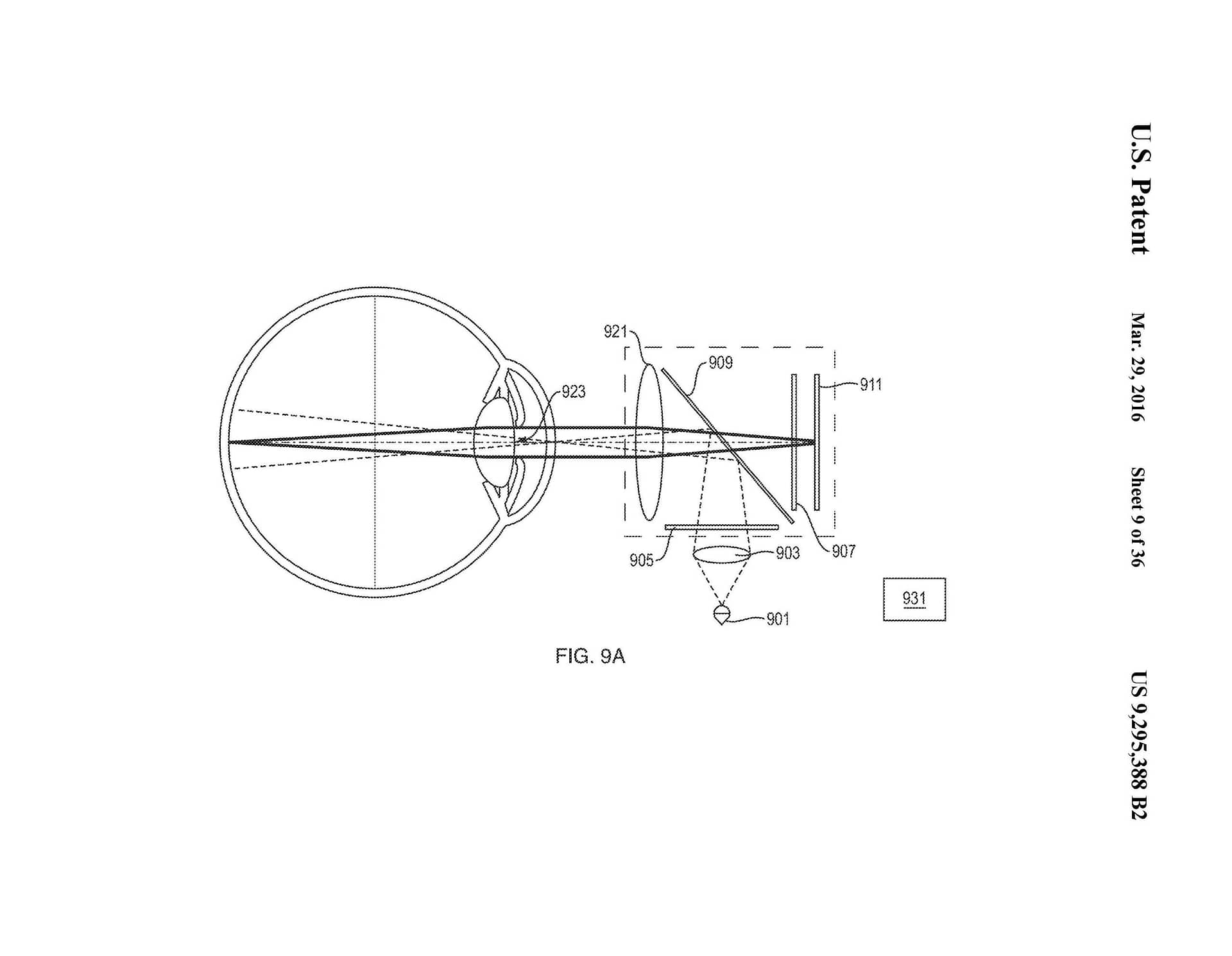

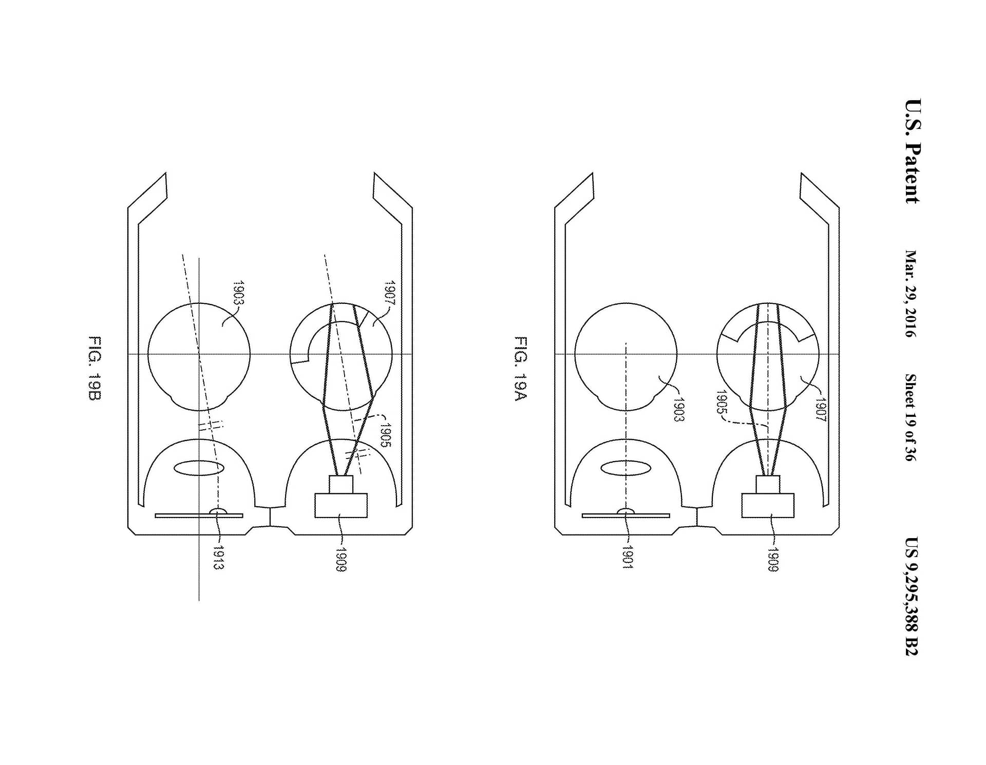
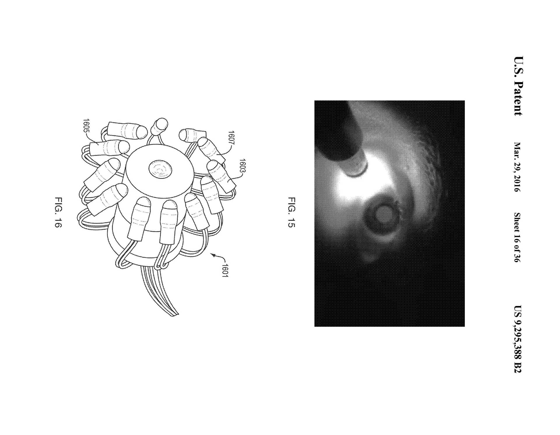
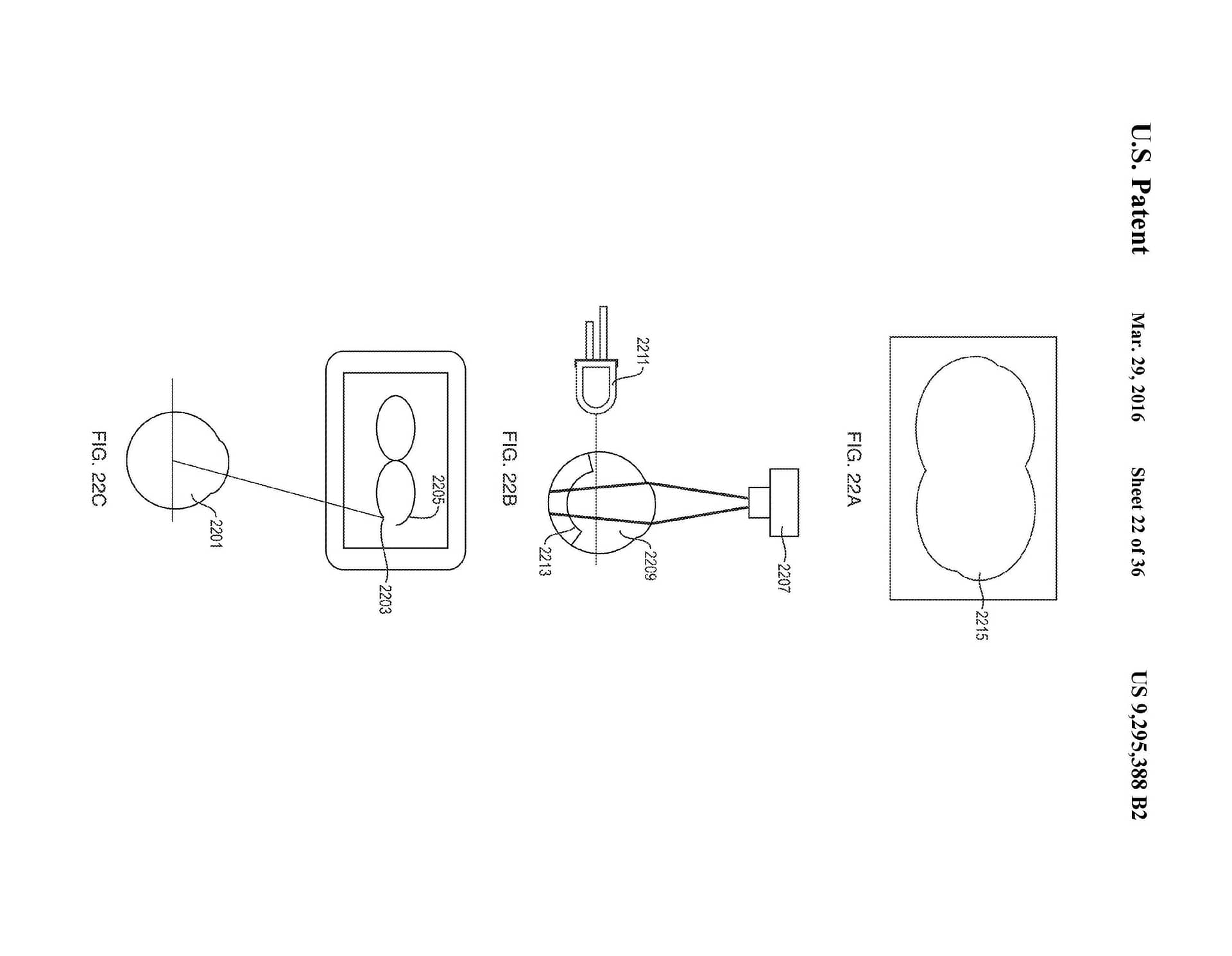
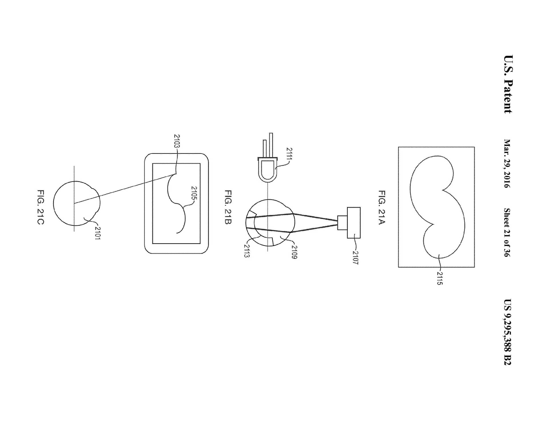
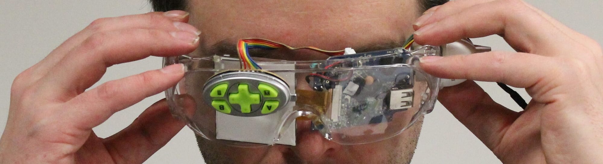
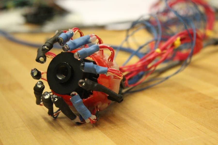
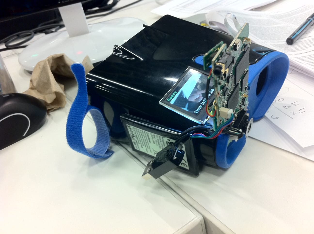
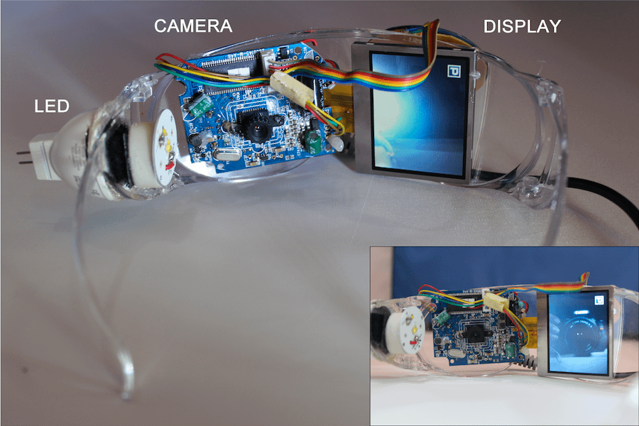
This invention comprises an apparatus for retinal self-imaging. Visual stimuli help the user self-align his eye with a camera. Bi-ocular coupling induces the test eye to rotate into different positions. As the test eye rotates, a video is captured of different areas of the retina. Computational photography methods process this video into a mosaiced image of a large area of the retina. An LED is pressed against the skin near the eye, to provide indirect, diffuse illumination of the retina. The camera has a wide field of view and can image part of the retina even when the eye is off-axis (when the eye’s pupillary axis and cameras optical axis are not aligned). Alternately, the retina is illuminated directly through the pupil, and different parts of a large lens are used to image different parts of the retina. Alternately, a plenoptic camera is used for retinal imaging.
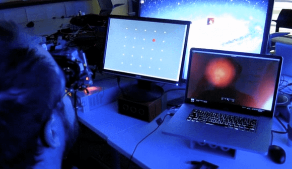
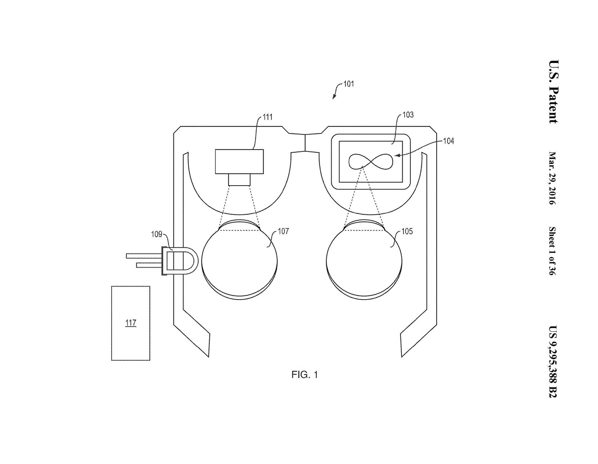
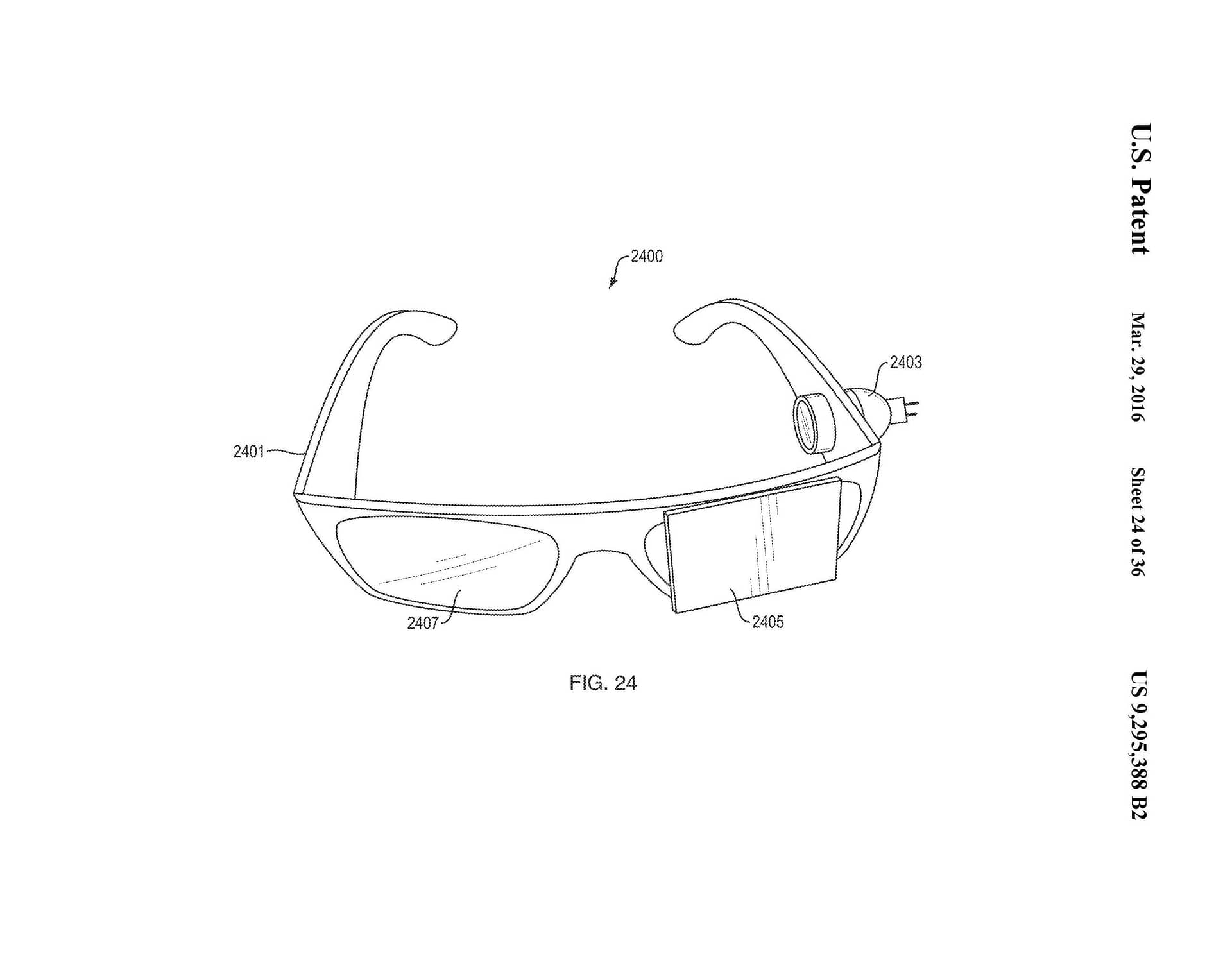
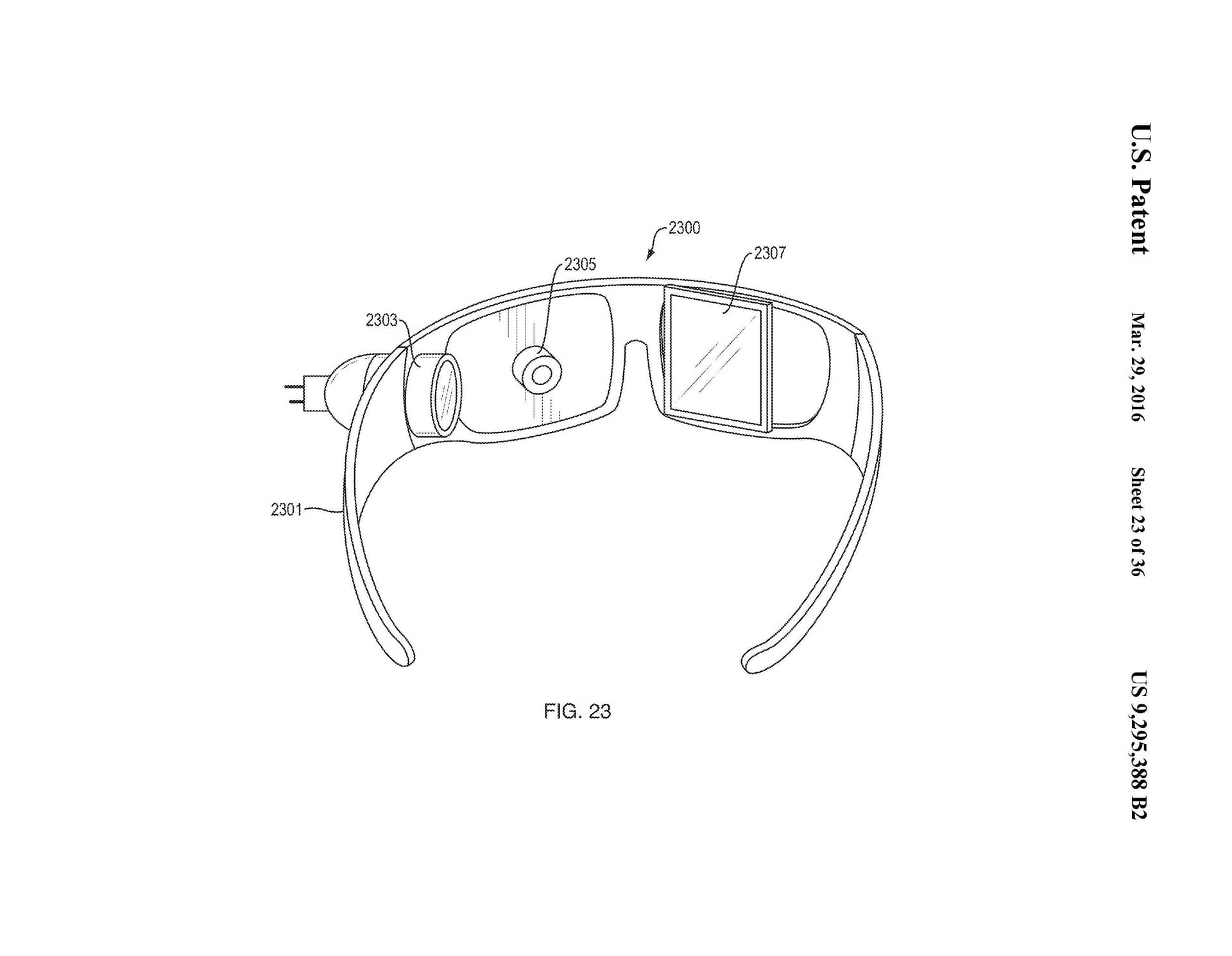
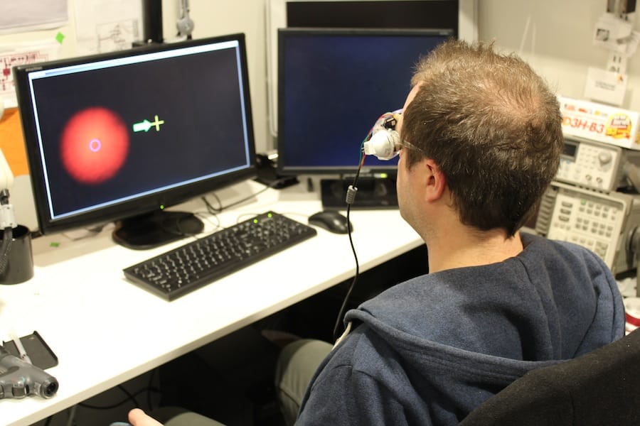
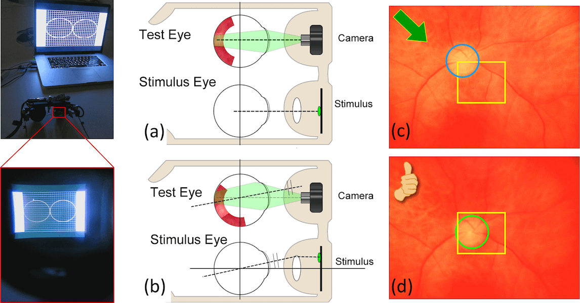
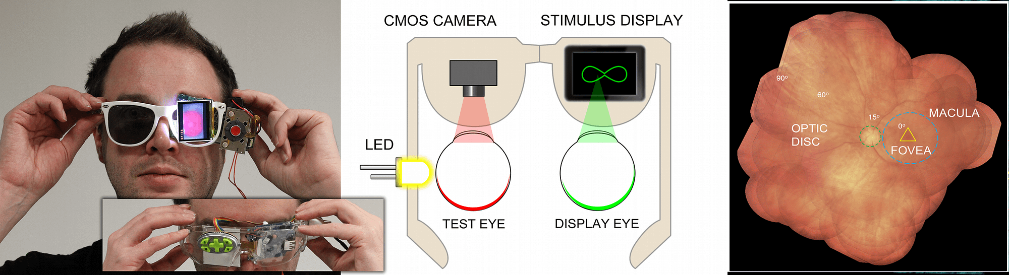
In an initial alignment step, the imaging device displays real-time visual feedback to one eye (the stimulus eye) of a user. The visual feedback is indicative of (i) the pupillary axis of the user’s eye that is being imaged (the test eye) and (ii) the optical axis of the device’s camera. For example, an LCD in the device may display visual feedback that comprises a circle representative of the optic disc of the test eye (which serves as an approximate indication of the pupillary axis) and a square indicative of the center of the camera (which serves as an approximate indication of the optical axis of the camera). This real-time visual feedback guides the user as the user changes direction of gaze in order to self-align the two axes. Once the two axes are aligned, the imaging device displays a video of moving visual stimuli to the stimulus eye. The user’s stimulus eye tracks this moving stimuli.
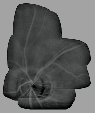
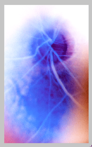
Due to bi-ocular coupling, the test eye moves (rotates) in a similar path. As the test eye rotates into different positions, a camera in the device captures multiple images of different portions of the retina of the test eye. Each of these images may capture only a small portion of the retina. These images are processed and stitched together to form an image of a large area of the retina. This large field of view (FOV) image of the retina can be displayed to the user in real-time. As the test eye rotates (while bi-ocularly coupled to the stimulus eye), the test eye moves into many rotational positions in which the test eye is “off-axis’ with respect to the camera. As used herein: (i) an eye is “off-axis’ with respect to a camera if the optical axis of the camera is not pointed at the pupil of the eye; and (ii) an eye is “on-axis’ with respect to a camera if the optical axis of the camera is pointed at the pupil of the eye. The camera has a wide FOV and thus can capture an image of at least a small part of the retina, even when the test eye is off-axis.
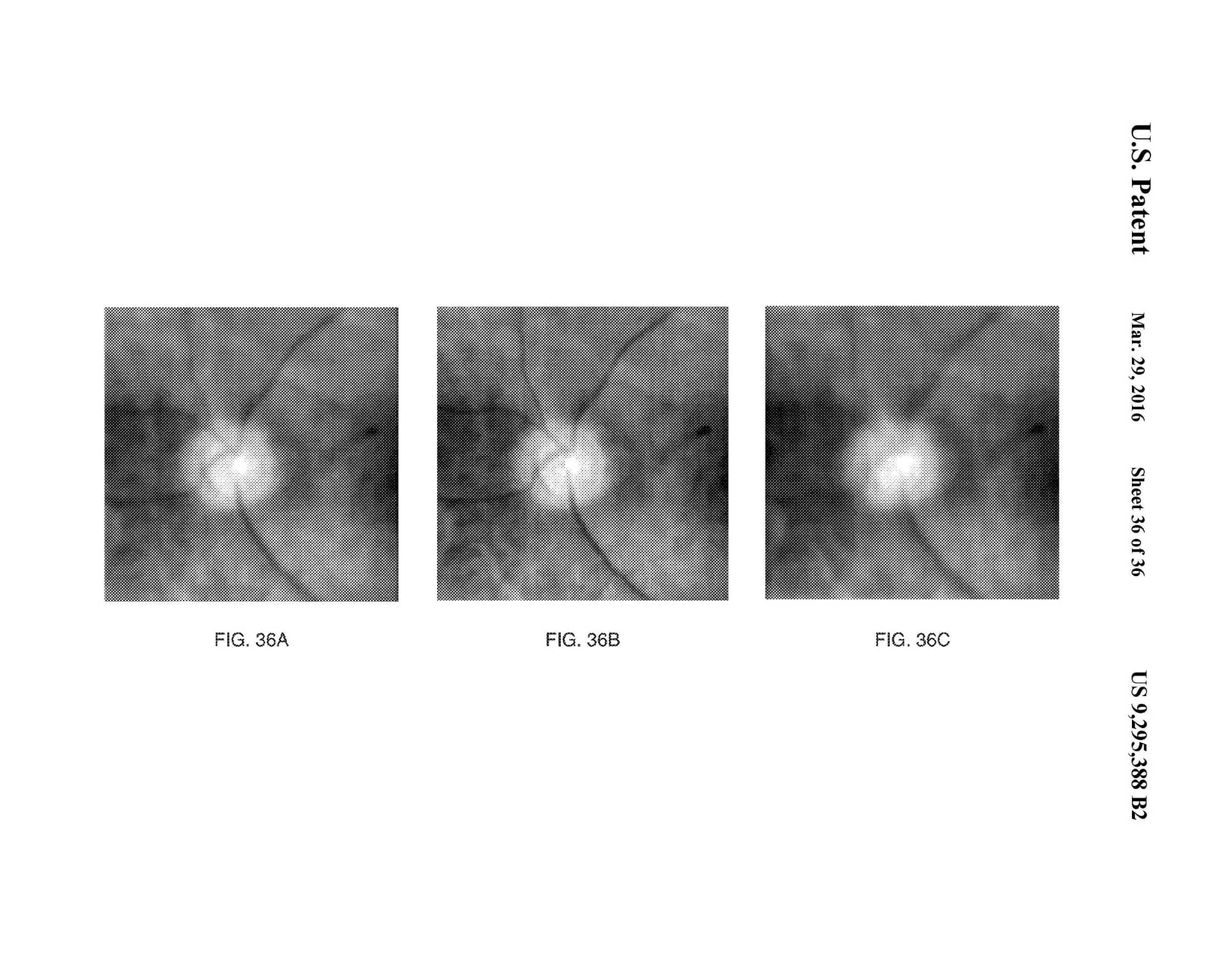
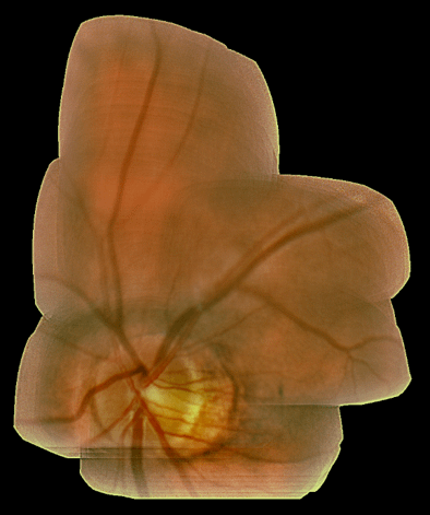
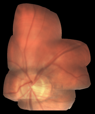
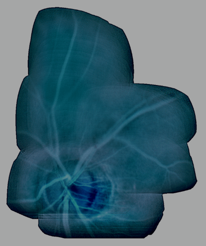
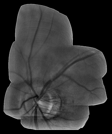
Results:
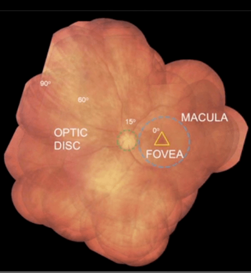
Results DIRECT ILLUMINATION:
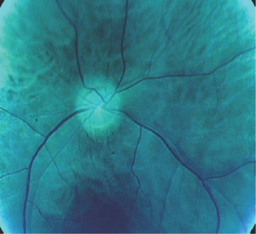
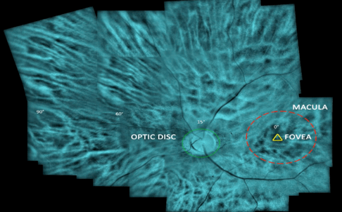
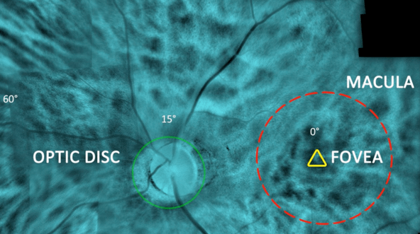
Results INDIRECT ILLUMINATION: